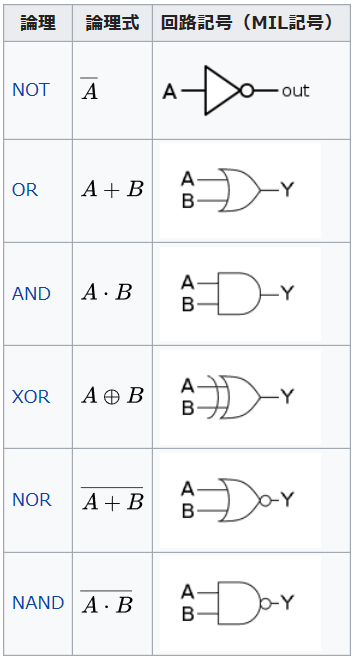
コンピュータは「論理回路」の組み合わせてできている

参考)https://ja.wikipedia.org/wiki/論理回路
[speech_bubble type="std" subtype="L1" icon="itokuma-normal.png" name="しげちゃん先生"]では、wikipediaに記載されている、論理回路を上から順にみていきましょう。
[/speech_bubble]
[speech_bubble type="std" subtype="R1" icon="sanoyu-normal.png" name="新人Y子"]はい。
[/speech_bubble]
[speech_bubble type="std" subtype="L1" icon="itokuma-normal.png" name="しげちゃん先生"]まず、一番上にある回路、「NOT」です。
[/speech_bubble]
[speech_bubble type="std" subtype="R1" icon="sanoyu-normal.png" name="新人Y子"]否定の「NOT」ですか?
[/speech_bubble]
[speech_bubble type="std" subtype="L1" icon="itokuma-normal.png" name="しげちゃん先生"]そうです。否定をする回路です。
回路記号は、


見方は、左側の「A」が入力信号で、右側の「out」が出力信号です。
[/speech_bubble]
[speech_bubble type="std" subtype="R1" icon="sanoyu-normal.png" name="新人Y子"]入力と出力からできているのですか?
[/speech_bubble]
[speech_bubble type="std" subtype="L1" icon="itokuma-normal.png" name="しげちゃん先生"]その通りです。ちなみに他の回路も同様に、入力と出力からできています。
[/speech_bubble]
[speech_bubble type="std" subtype="R1" icon="sanoyu-normal.png" name="新人Y子"]どのような信号が入力されるのでしょう?
[/speech_bubble]
[speech_bubble type="std" subtype="L1" icon="itokuma-normal.png" name="しげちゃん先生"]1ビットの値が入力されます。
[/speech_bubble]
[speech_bubble type="std" subtype="R1" icon="sanoyu-normal.png" name="新人Y子"]ということは、「0」または「1」が入力されるという事ですか?
[/speech_bubble]
[speech_bubble type="std" subtype="L1" icon="itokuma-normal.png" name="しげちゃん先生"]はい、その通りです。実際は、数字の「0」と「1」に対応する電圧です。
例えば、5V系のシステムであれば、「0」は0ボルト、「1」は5ボルトのようになっています。
[/speech_bubble]
[speech_bubble type="std" subtype="L1" icon="itokuma-normal.png" name="しげちゃん先生"]さて、NOT回路は反対の答えを返す回路です。
Aに「0」が入力されたら、outに「1」が出力されます。
Aに「1」が入力されたら、outに「0」が出力されます。
[/speech_bubble]
*下図は、あくまで反対の動作をイメージするための図です。


[speech_bubble type="std" subtype="R1" icon="sanoyu-normal.png" name="新人Y子"]へぇー
[/speech_bubble]
[speech_bubble type="std" subtype="R1" icon="techtrageman-normal.png" name="テクトレージマン"]次回に続く[/speech_bubble]


